
1
ROUTE PLANNER TRAINING GUIDE
July 26, 2017
Version 3.0

2
TABLE OF CONTENTS
CHAPTER 1: Introduction ....................................................................................................................... 4
About Route Planner ........................................................................................................................... 4
This Manual… ..................................................................................................................................... 4
CHAPTER 2: Logging In (STANDALONE MODE) ................................................................................... 5
CHAPTER 3: Route Planner Navigation Overview .................................................................................. 6
Stand Alone Mode ............................................................................................................................... 6
Integrated Mode .................................................................................................................................. 6
What is New? ...................................................................................................................................... 7
Cornerstone Panel ............................................................................................................................. 13
Upper Tool Bar .............................................................................................................................. 13
Routing Section ............................................................................................................................. 14
Routing Specifics ........................................................................................................................... 16
Driving Directions ........................................................................................................................... 17
Vehicle Information ............................................................................................................................ 18
Navigation Toolbar............................................................................................................................. 19
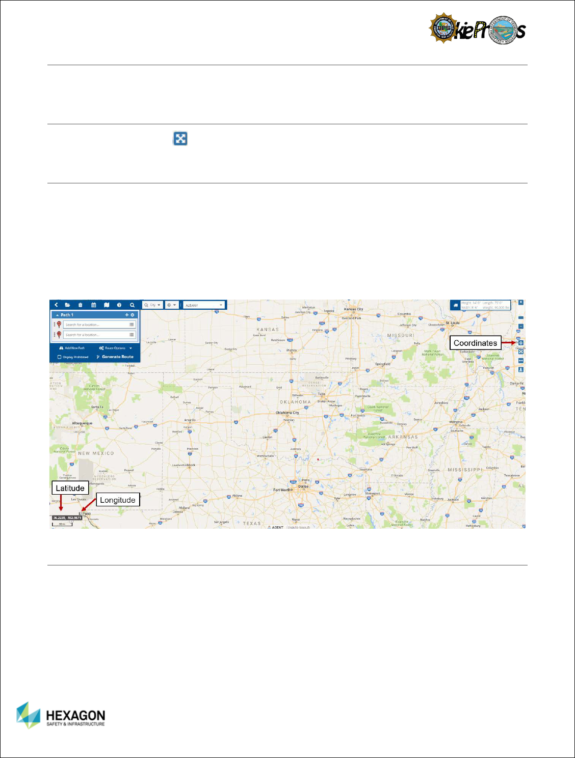
Map Scale and Map Coordinates ....................................................................................................... 19
User Name | Log Off | Route Planner Version .................................................................................... 19
Google Information | Terms | Report a Google Problem ..................................................................... 20
Map ................................................................................................................................................... 20
CHAPTER 4: Map Navigation Overview ................................................................................................ 20
Find Toolbar ...................................................................................................................................... 20
Zooming In and Out ........................................................................................................................... 21
Zoom in and out Using the Mouse .................................................................................................. 21
Zoom in and out Using Navigational Controls ................................................................................. 21
ZOOM By Rectangle ...................................................................................................................... 21
Panning the Map ............................................................................................................................... 22
Centering the Map ............................................................................................................................. 22
Displaying Coordinates ...................................................................................................................... 22
Distance Map Scale Level.................................................................................................................. 22
Map Displays ..................................................................................................................................... 24
Map Layers .................................................................................................................................... 24
Display Order ................................................................................................................................. 26
Base Maps..................................................................................................................................... 26
CHAPTER 5: Routing Overview ............................................................................................................ 29
Routing overview ............................................................................................................................... 29
Route Evaluation ............................................................................................................................... 29

3
Prohibited Route ................................................................................................................................ 29
Restrictions ........................................................................................................................................ 30
Alternate Routes ................................................................................................................................ 31
Impedance Models ............................................................................................................................ 32
Directions Panel ................................................................................................................................ 32
Mapped Route ................................................................................................................................... 33
Vehicle Information ............................................................................................................................ 34
Bridging ............................................................................................................................................. 35
Clear Route ....................................................................................................................................... 36
Print Route ........................................................................................................................................ 36
CHAPTER 6: Building a Route .............................................................................................................. 37
Build the route ................................................................................................................................... 37
Generate the route............................................................................................................................. 37
Locate Options available in the Routing Panel ................................................................................... 38
Map Click ....................................................................................................................................... 38
Street Address ............................................................................................................................... 38
Intersects With (Street Intersection) ............................................................................................... 39
Coordinates ................................................................................................................................... 39
Locate Options available in The Map ................................................................................................. 39
Set Origin ...................................................................................................................................... 40
Add Via Point ................................................................................................................................. 40
Set Destination .............................................................................................................................. 40
Restriction Within radius ................................................................................................................ 40
Street View ........................................................................................................................................ 40
Saved Routes Overview .................................................................................................................... 40
Saved routes ................................................................................................................................. 41
Locate a Stop – Recent | Favorite | Boundary | Zoom To .................................................................... 41
Recent ........................................................................................................................................... 42
Favorites ........................................................................................................................................ 42
Boundary ....................................................................................................................................... 42
Zoom To ........................................................................................................................................ 43
APPENDIX A: Terminology ................................................................................................................... 44
APPENDIX B: Report Problems ............................................................................................................ 44

4
CHAPTER 1: INTRODUCTION
ABOUT ROUTE PLANNER
The Route Planner application gives authorized staff the ability to quickly determine the safest route for
oversized and overweight (OS/OW) vehicles. Unfortunately, when it comes to carrying oversize and
overweight loads, the shortest route is not always the safest. To ensure safe movement of oversize loads
and overweight loads the Route Planner application evaluates the vehicle dimensions against the
restrictions on the network. It is designed to generate a safe, efficient route for the vehicle while avoiding
any roadway restrictions.
The Route Planner application offers a variety of intuitive options to define the route. The user can define
the route’s origin, destination, and intermediate stops using a combination of options such as map click,
street address, intersects with, or coordinates. The user can also save commonly used routes and recall
them to expedite the routing process.
THIS MANUAL…
This manual is intended to use as a training guide and a reference guide for the day-to-day operations of
the Route Planner application. It is designed to help the user quickly learn about the application and its
features, as well as share tips to help the user use Route Planner to its fullest potential.
This Guide will instruct how to do the following:
1. Login to Route Planner
2. Navigate Route Planner
3. Locate a Stop
4. Build a Simple Route (Origin and a Destination)
5. Build a Complex Route (Via Points)
6. Route an Oversize Vehicle
7. Route an Oversize/Overweight Vehicle
8. Manage Saved Routes
9. Print a Route
Upon completion of the training, personnel will be familiar with all the steps necessary to determine the
safest route for a vehicle using the Route Planner application.
5
CHAPTER 2: LOGGING IN (STANDALONE MODE)
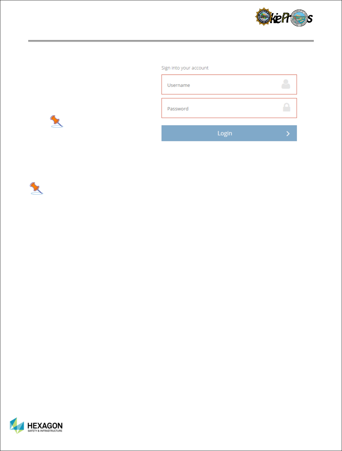
To Login to the Route Planner application in standalone mode:
1. Enter the
Login ID in the
username text box.
2. Enter the
Password in the
password text box.
3. Select the Login button.
Note:
If the user has
trouble logging in, contact the
System Administrator.
If the login information the user entered is valid, the system will display the home page for the Route
Planner application.
Note: If you are using Routing component as part of OkiePros, login into OkiePros and select
any of the route options to transition to Route Planner application.
6
CHAPTER 3: ROUTE PLANNER NAVIGATION OVERVIEW
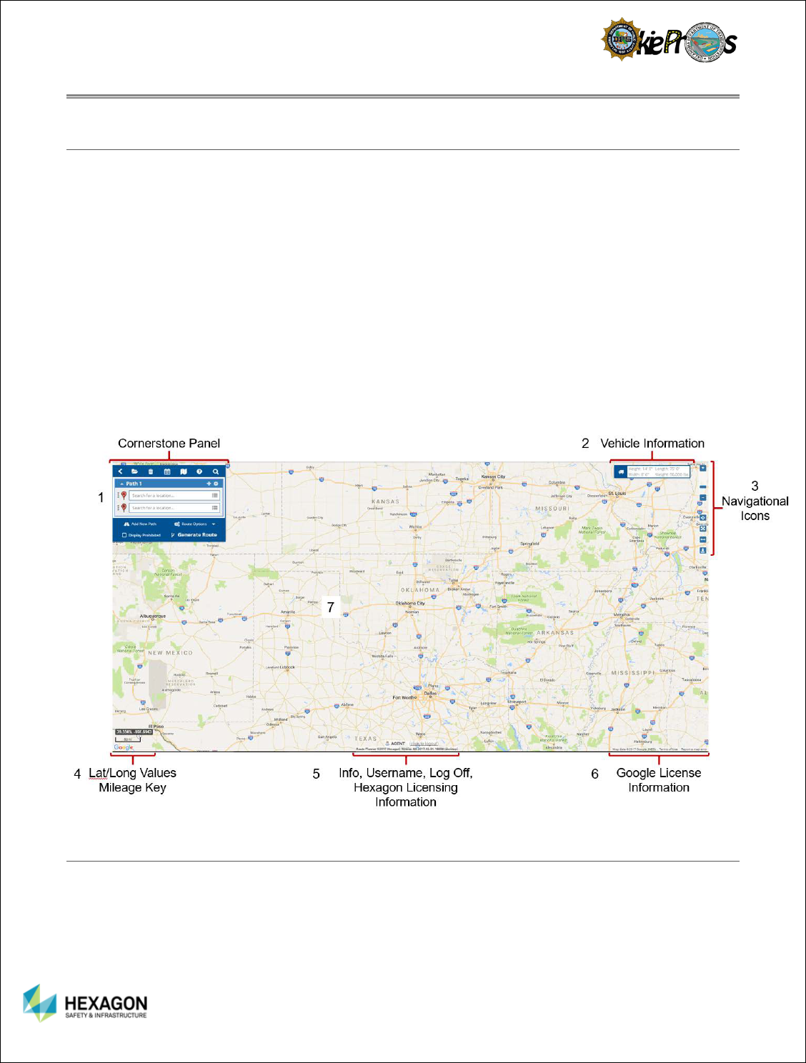
STAND ALONE MODE
The Stand Alone Mode for Route Planner application is divided into these sections:
1. Cornerstone–It is comprised of the Routing section and once the route is generated, driving directions
are displayed.
2. Vehicle Information – The vehicle dimensions, configuration type, bridge posting, weight classification,
number of axles, and other items pertaining to the OSOW vehicle defined in the permitting process.
3. Navigational Icons – Zoom functions, coordinate information, center map, measure, and street view.
4. Latitude and Longitude Coordinates and Mileage Scale – Lat/Long readings will change as the cursor
moves around the map. Mileage Scale will change with the zoom function.
5. Username, Log Off, Hexagon Licensing Information
6. Licensing Information – Map Data, Terms of Use, and Report a Map Error (used for Google Maps).
7. Map of the State
INTEGRATED MODE
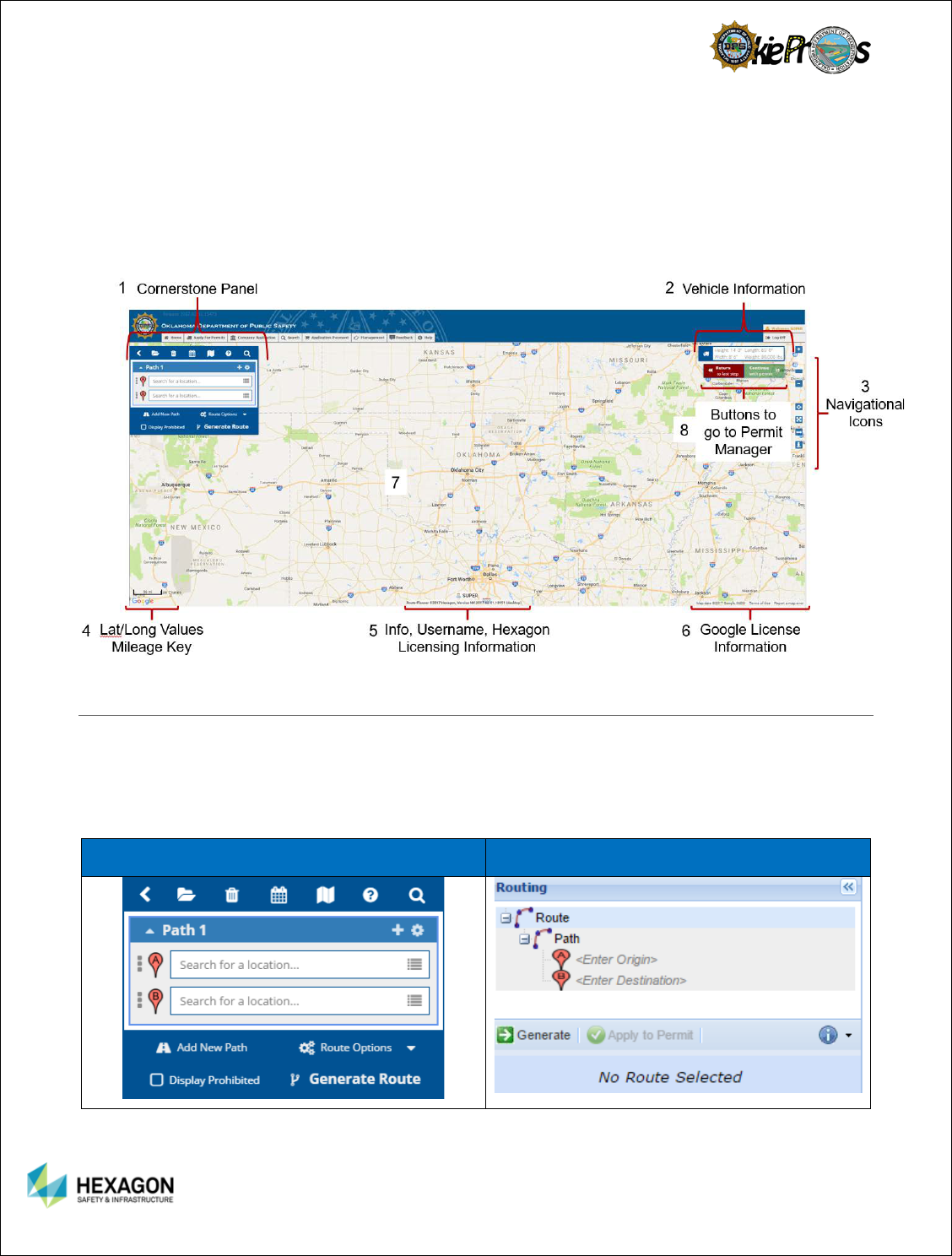
The Integrated Mode for Route Planner application is divided into these sections:
1. Cornerstone–It is comprised of the Routing section and once the route is generated, driving directions
are displayed.
2. Vehicle Information – The vehicle dimensions, configuration type, bridge posting, weight classification,
number of axles, and other items pertaining to the OSOW vehicle defined in the permitting process.
7
3. Navigational Icons – Zoom functions, coordinate information, center map, measure, and street view.
4. Latitude and Longitude Coordinates and Mileage Scale – Lat/Long readings will change as the cursor
moves around the map. Mileage Scale will change with the zoom function.
5. Username, Log Off, Hexagon Licensing Information
6. Licensing Information – Map Data, Terms of Use, and Report a Map Error (used for Google Maps).
7. Map of the State
8. Return or Continue to the Permit Manager
WHAT IS NEW?
The new Route Planner Application has a different routing panel with the features previously found on the
ribbon bar. In the Route Planner (New) Application, the routing panel is smaller to allow more of the map
to display. Since the Ribbon Bar has been removed in Route Planner (new) Application, most of the
functions are available. The table below will highlight some of the changes, new features, and removed
features.
Route Planner (New)
Route Planner
8
Route Planner (New)
Route Planner
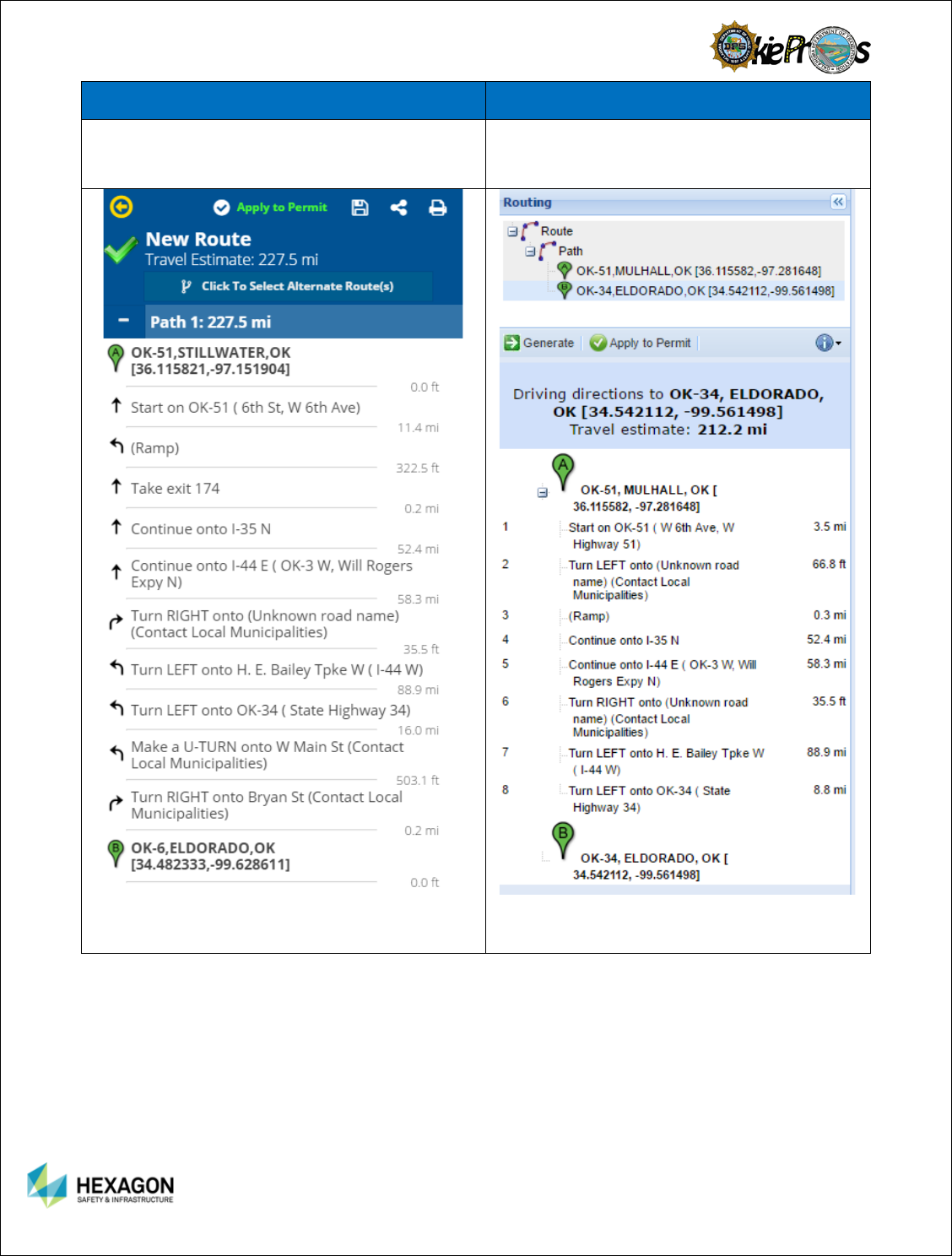
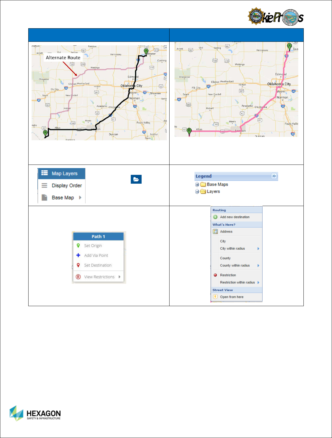
Many of the features on the new Cornerstone
Panel replaces the Ribbon Bar to give the user a
more compact view of the map and features.
When the route is generated, the cornerstone
panel turns into the driving directions.
When the route is generated, the routing panel
expands to provide driving directions.
9
Route Planner (New)
Route Planner
Alternate Route may be turned on or off for
different roles in the System Manager.
The application allowed the user to pick different
impendance models but not show all of them on
the route.
These legend is replaced by
selecting the on the
upper toolbar of the
Cornerstone Panel.
The righ click options for the map in the new
application:

10
New Feature or Improved Features
Information
Recent – Recent Stops defined a
respective user.
Favorites – ability for a user to use
their favorite stops and with an optional
unique name.
Boundary – Predefined boundaries for
states to help users pick boundaries for
stops. Only management users have
the ability to modify the list.
Mark Favorite – abilty for the user to
define favorite stops.
Clear – erases the stop information
and it does not resize the map or clear
out other stop inputs.
In Stand Alone Mode the user may
apply a specified route to a permit, if
the user knows the permit number.
The user may enter either a street
address, point of interest, or coordinate
information directly into the stop input
bars. This allows the user to bypass
the menu of options such as map click,
street address, et al.
Instead of right clicking in the older
version of Route Planner, the user may
select the street view from the
navigational area in Route Planner
(new).
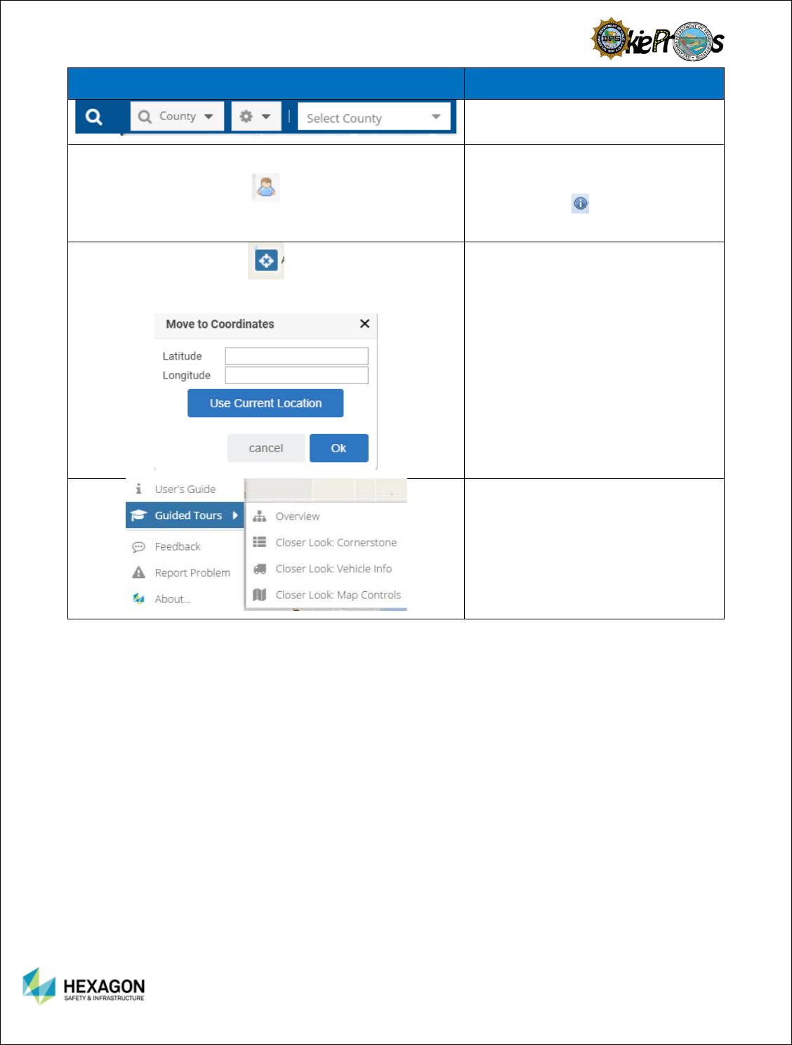
The location of the find toolbar has
been collapsed by default into the
Cornerstone Panel. The user will need
to select the Find Icon, and then the
find toolbar information will expand to
display the information.
11
New Feature or Improved Features
Information
The information button has been
moved to the bottom center of the
map. In the older application, the
information icon was found on the
routing panel.
Select the Coordinates Icon on the
Navigational Tool Bar.
Once selected, the user can enter
coordinates directly or they can use
their current physical location (if the
users have properly set their privacy
settings).
Guided Tours always the users to have
tours to show different features and
functions in the Route Planner (New).
Including the cursor and messages are
placed at the location of the feature
described.
12
New Feature or Improved Features
Information
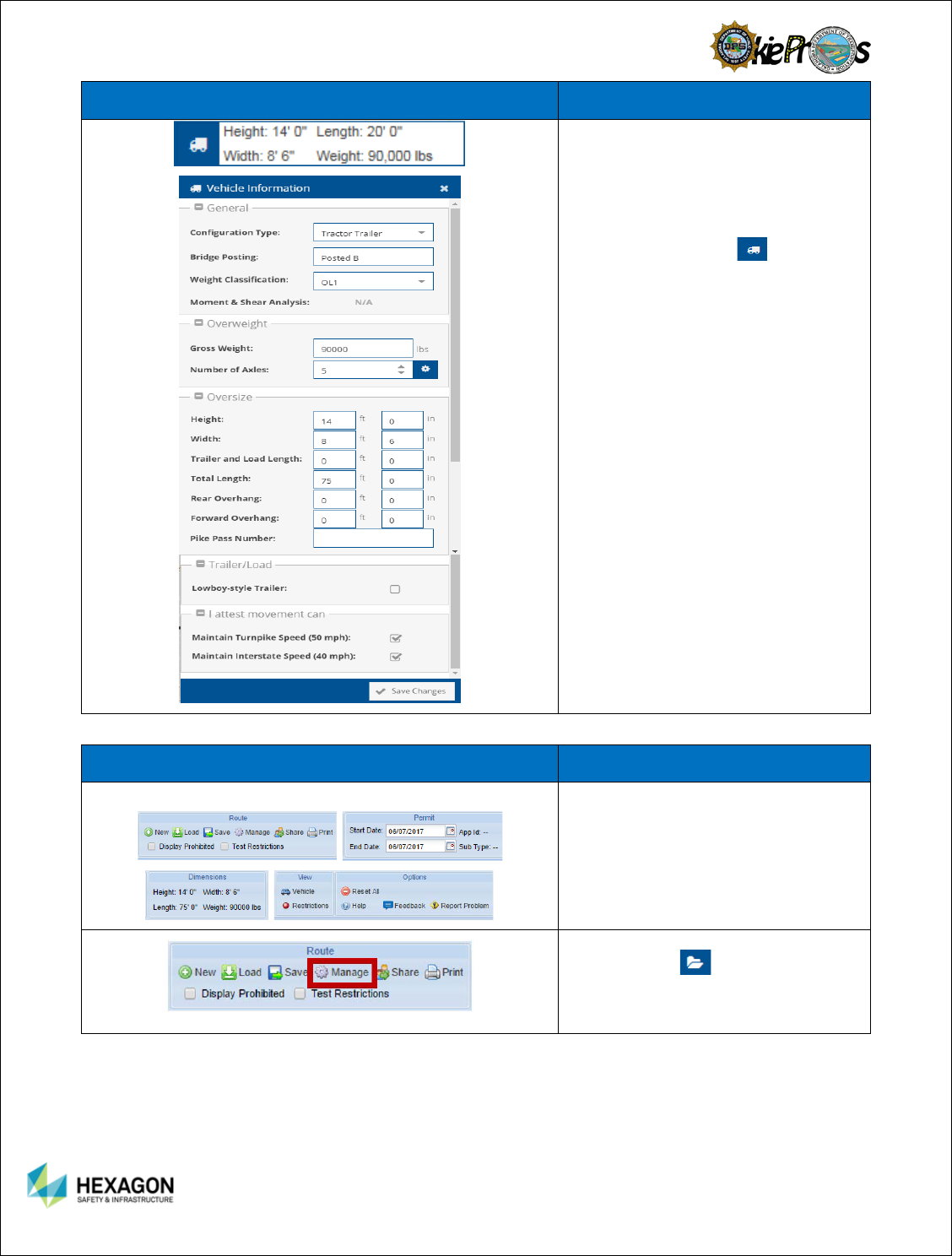
The vehicle information is found on the
top, right part of the map near the
navigational tools. In the older
application, the vehicle information was
found in the ribbon bar. To access the
vehicle information in detail, the user
clicks on the truck icon in the
summary vehicle information. The
detail panel of vehicle information
works identically to the older
Application.
Changed/Deprecated Features Information
Ribbon Bar from the older Route Planner
The ribbon bar is no longer a feature in
Route Planner (New). The features
are available but most are in the
Cornerstone Panel or along the edges
of the Map.
Manage button is no longer relevant.
The Load Icon handles both
saving and editing routes.
13
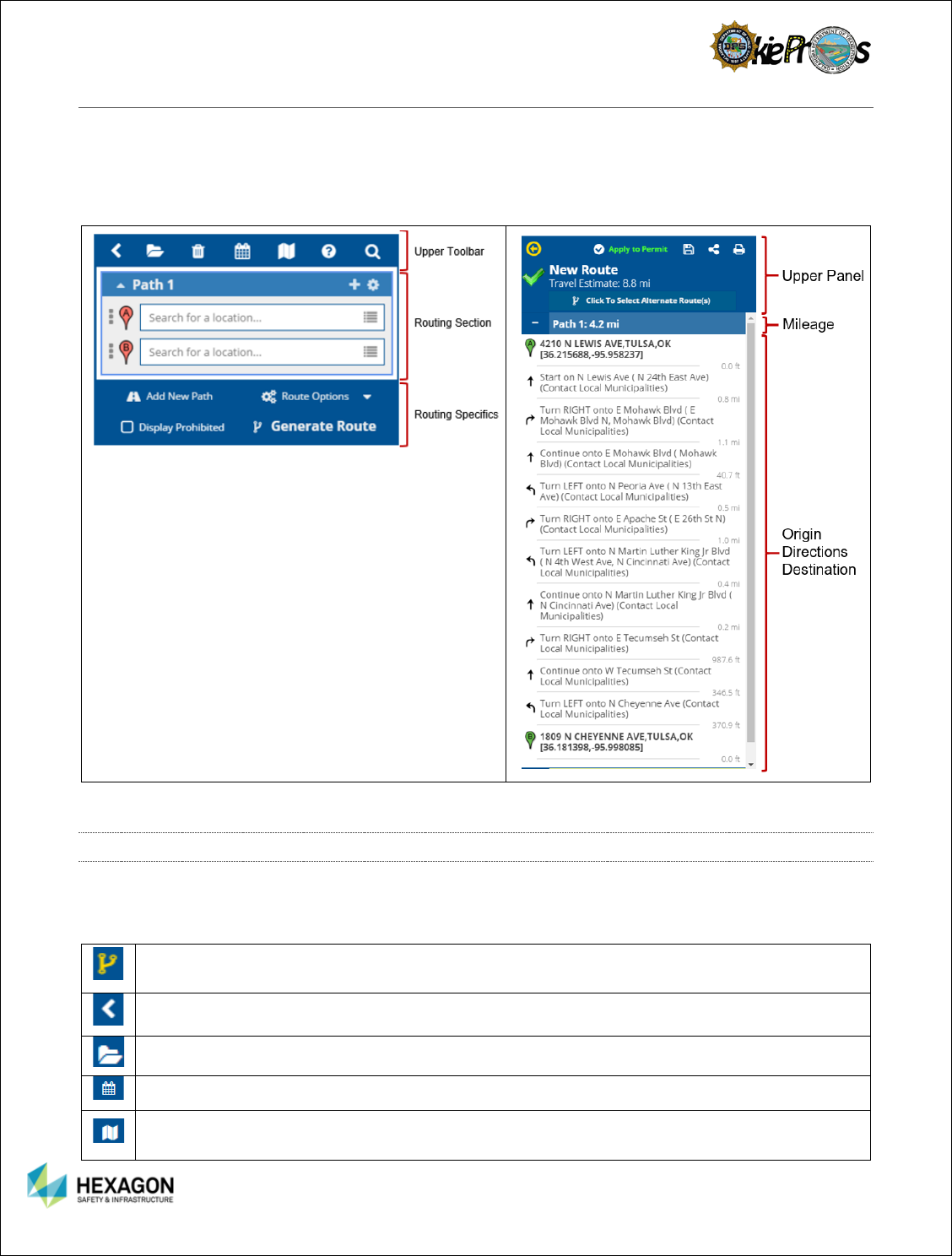
CORNERSTONE PANEL
The Cornerstone Panel is comprised of: Upper Toolbar, Routing Section, and Routing Specifics. The
Routing section is intended to support building the route and generating the route.
Once a successful map has been generated, the Driving Directions section will display. The Driving
Directions panel is intended to display the driving directions, save/share/print route, and define alternate
impedance route.
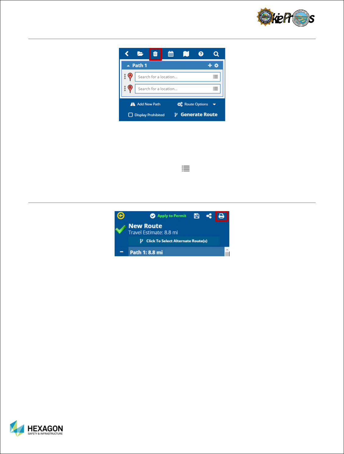
UPPER TOOL BAR
The Upper Toolbar includes functions for loading saved routes, deleting all inputs, selecting permit dates,
map layers, help and search. If a successful route has been generated, there is an option to go back to
the driving directions.
Return to Driving Directions - Appears only when a successful route has generated. Allows the
user to go back to the driving directions panel.
Collapse Cornerstone Menu
Load Route – gives the user the ability to load a previously saved route.
Permit Dates – if permitted, allows the user to amend or add permit start and end dates.
Map Displays
Map Layers include OSOW Roads, Designated Truck Routes, and Stops.
14
Display Order provides the user with the Map Layer order.
Base Map Selection provides different map views for the user.
Gives the user multiple ways to seek help with the application:
User’s Guide
Guided Tour
Site Overview
Create a Route Help
Feedback – survey system to handle user’s satisfaction with the application
Report Problem – gives the user a way to report problems to the system administrator.
About – License information and license agreements.
Find Toolbar
County
City
District
Troop
Township
Roads (interstate, US Highway, and State Highways)
Note: to retract Find Toolbar, select again.
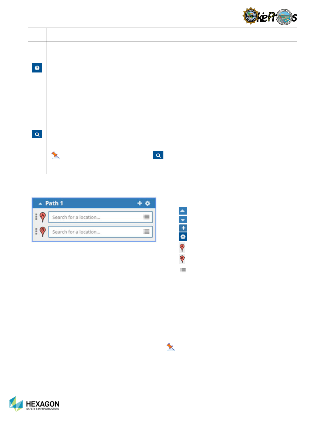
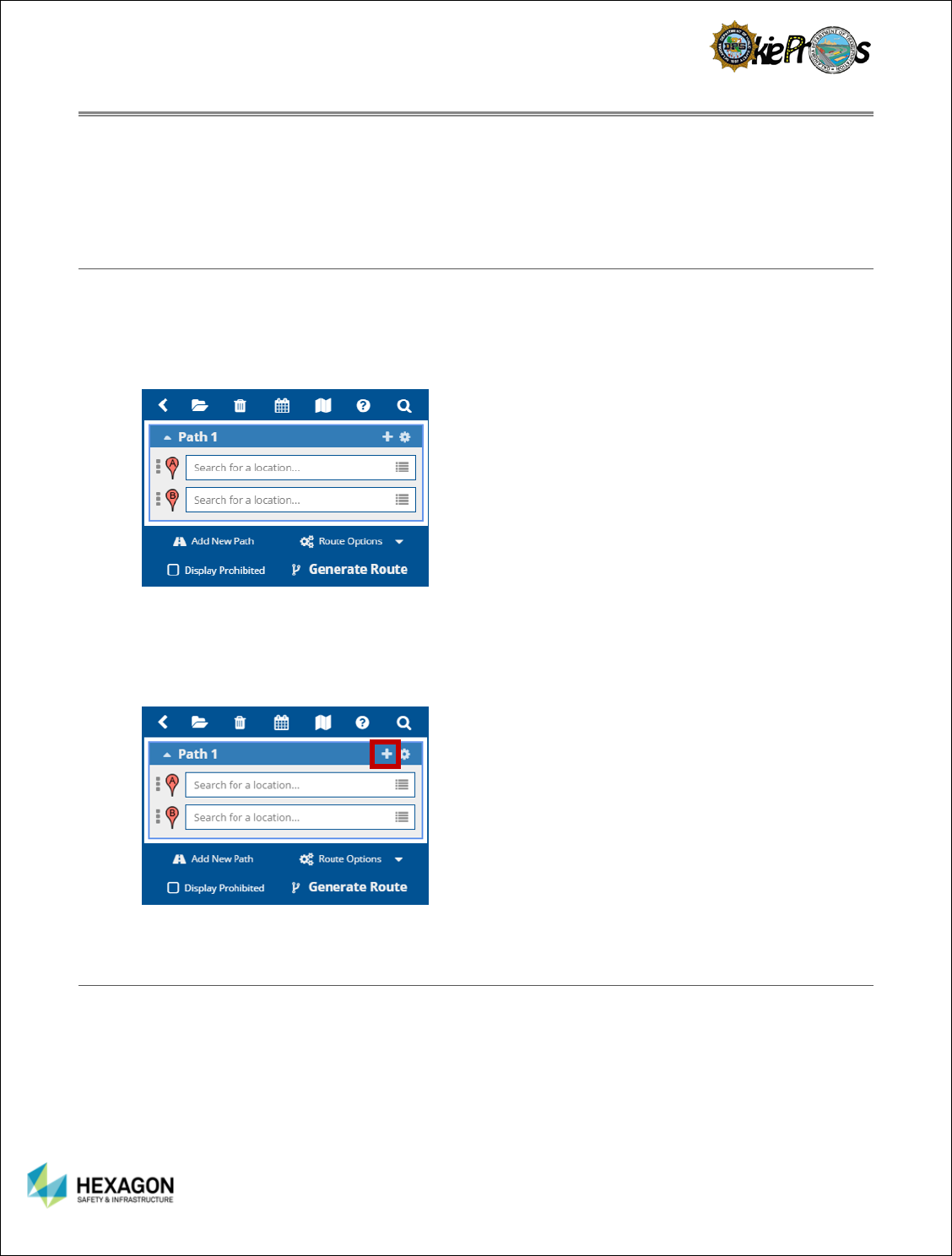
ROUTING SECTION
Routing Section:
Collapse Path Name
Expand Path Name
Add Via Point or a Special Instruction.
Rename, Reset, and Optimize Route.
Input Origin.
Input Destination.
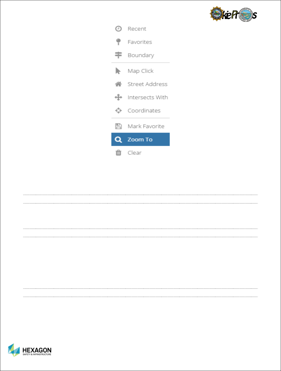
Methods to enter stops.
Recent
Favorites
Boundary
Map Click
Street Address
Intersects with
Map Coordinates
Mark Favorite
Move To
Clear
Note: The clear function is different than
delete. Only the data in the stop is erased.
15
Below are the functions available in the Routing section:
The Generate option is used to generate the route. To generate a route, the user need to enter at least
two stops (an origin and a destination). The first stop is treated as the origin, and the last as the
destination. Once the user has the stops defined, click the Generate to generate the route.
DIRECTLY ENTERING
STOPS
A more intuitive addition to the latest Route Planner application
includes the ability to directly enter stops into the Routing inputs. For
example, the user may enter an address or coordinate points directly
into fields associated with each stop.
TO DETERMINE IF A
STOP HAS BEEN
LOCATED ON THE
ROADWAY NETWORK…
If a stop has been located on the roadway network, it will appear
with a located marker ( ) in the Routing section. Alternatively,
if the stop has not yet been located on the roadway network, it
will appear with an un-located marker ( ) in the Routing
section. When the user select Generate, it will handle locating
the route stops prior to calculating the route. If the system was
able to locate each of the route stops, the mapped route and
directions will be displayed on the screen.
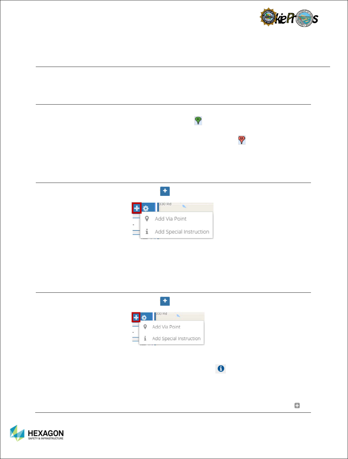
TO ADD A VIA POINT…
Select the in the routing section.
Adding a Via Point between the Origin and Destination causes
the route to follow the Via Points in the order that they are listed
in the route. Via placement is the most common method of
directing a route. The user can use as many Via Points as the
user would like to direct the route to go this way and not that
way.
ENTERING SPECIAL
INSTRUCTIONS
Select the in the routing section.
Adding a special instruction into the driving directions may help
the carrier’s driver with instructions specific to the route. The
special instruction will have an to indicate the instruction will
be placed at the end of the driving directions.
Once the route has been successfully generated, the user may
add special instructions along the driving route. Select a step in
the driving directions and right click on the instruction. The
16
will appear with Add Special Instruction. The instruction will be
inserted directly under the step selected.
Note: When locating a stop, if a single address is found, the system will automatically update
the stop detailed in the Routing section to display the full street address and set the marker to a
located marker ( ). If multiple addresses are found, the Locate Point dialog will be displayed
listing the best possible matches. The Route Planner Application will use Hexagon Logo or
Google Logo to identify which mapping application it used to generate the stop. To add the stop,
select an entry from the list and the stop will be automatically updated to appear with a located
marker ( ) in the Routing section. Be sure to select the option going in the correct direction of
traffic.
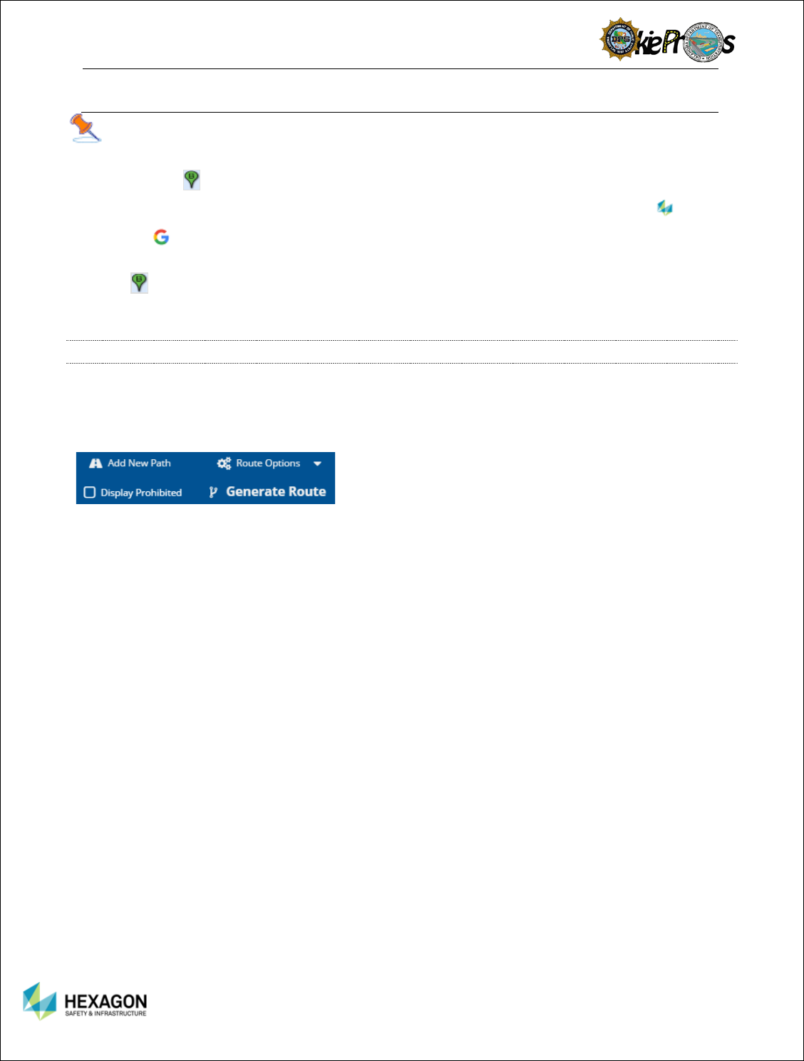
ROUTING SPECIFICS
Routing Specifics allow the user functions to make
specifically defined routes.
Add New Path – Allows the user to define additional
paths to the route.
Display Prohibited – Allows a route with restrictions to
generate.
Route Options
Avoid Turnpikes / Interstates
Test Restrictions
Add Alternate Routes – OSOW, OSOW Shortest, US
Highways, State Highways, and Local Roads.
Generate Route
17
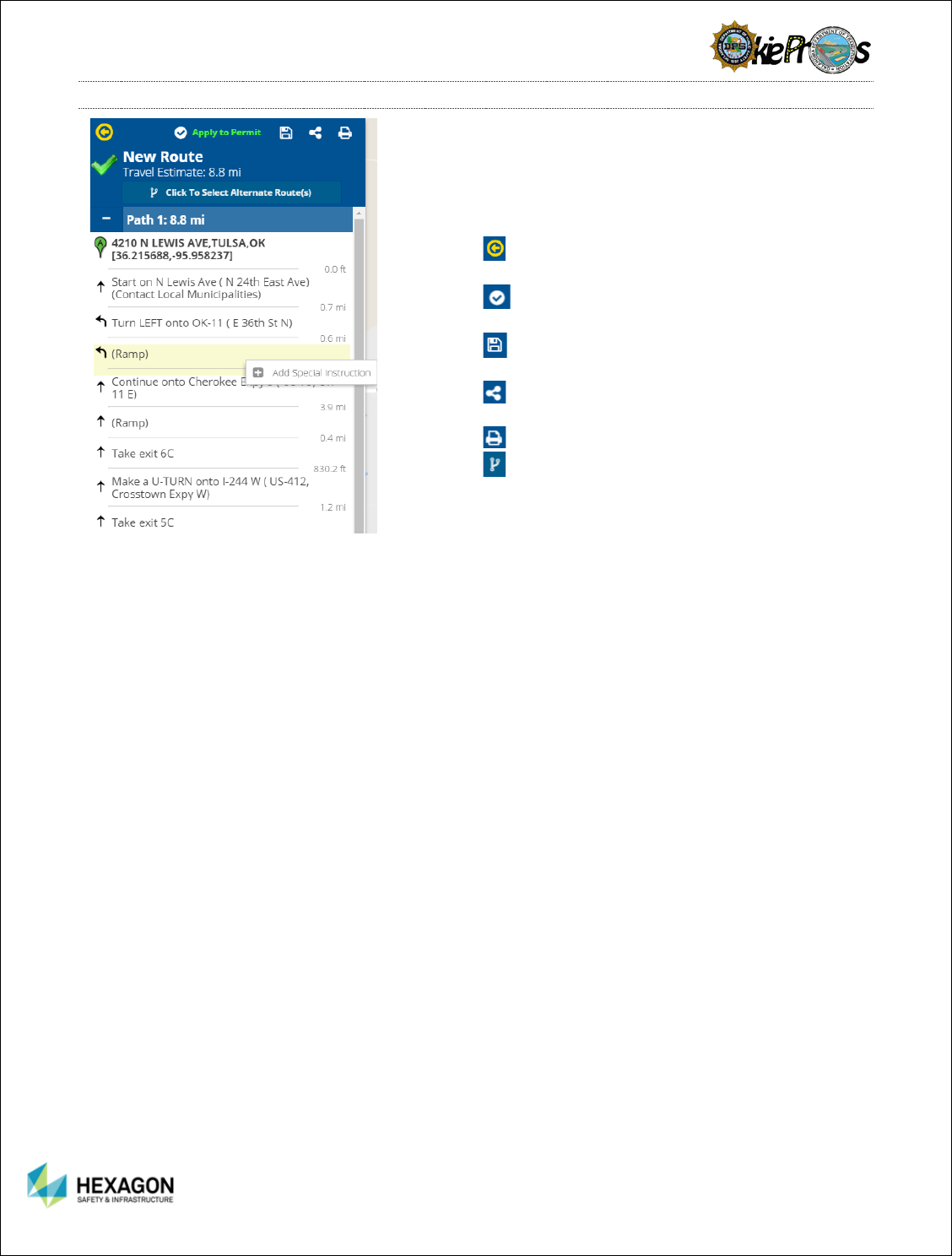
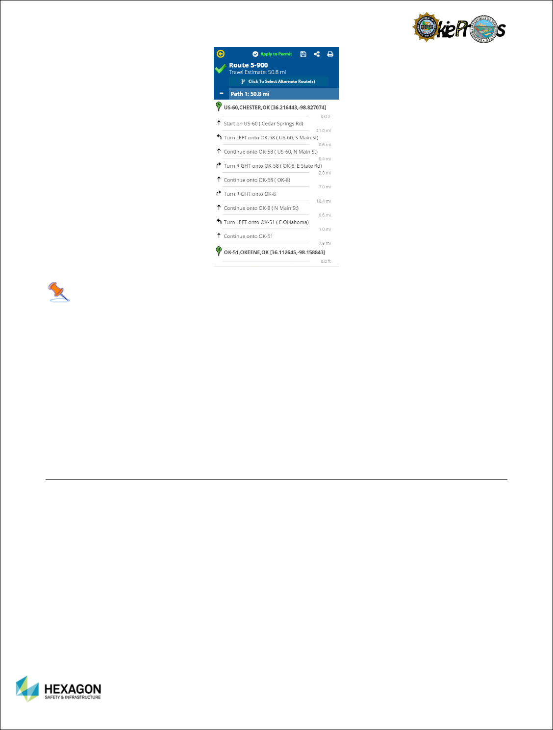
DRIVING DIRECTIONS
The Driving Directions section provides a step-by-step
breakdown of the driving directions. Included in the
section is the Upper Panel, Mileage, and the Step-by-
Step Driving Directions.
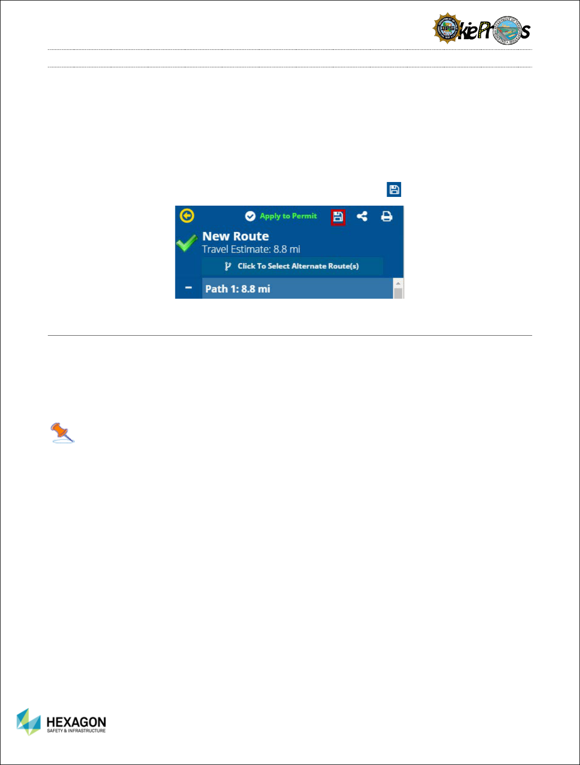
Upper Panel
Return to Cornerstone Panel – takes the user
back to the Cornerstone Panel.
Apply to Permit – allows the user to apply to
an existing permit if the Permit ID was known.
Save Route – especially helpful if a carrier
frequently uses the same route.
Share Route – allows the user to share a route
with other users.
Print Route
Alternate Routes – allows the user to pick
between routes based upon different impedance
route generation from OSOW, Local Roads, and
State Highways.
Travel Estimate - Estimated mileage for OSOW
Impedance Model
Mileage
Estimated mileage for the alternate route picked.
Step-By-Step Driving Directions
Origin and Destinations bookend the step-by step
directions
Step-by-Step Directions include the mileage on
each road and the directional arrows for the turns.
The user can click on any individual driving
instruction to zoom in and highlight the roadway
on the map.
The user can hover the mouse over any individual
driving instruction to display a tooltip detailing the
roadway name and total distance.
The user can right click on a driving instruction to
insert any special instructions that the user would
like to communicate to the driver.
18
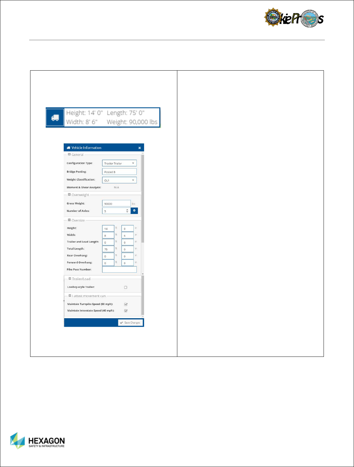
VEHICLE INFORMATION
The Vehicle Information is the information passed from Permit Manager to Route Planner. The
information is used to safely route a specified vehicle through the state. If the user is in the Route
Planner Stand-alone mode, the user may make edits to the Vehicle Information.
Vehicle Information
Vehicle Details
Vehicle Information includes the cursory
information on the vehicle: Height, Length, Width,
and Weight.
Select the Truck Icon to view the Vehicle Details
General
Configuration Type
Bridge Posting
Weight Classification
Moment and Shear Analysis
Overweight
Gross Weight
Number of Axles
Oversize
Height
Width
Trailer and Load Length
Total Length
Rear Overhang
Forward Overhang
Pike Pass Number
Moment and Shear Analysis
Trailer/Load
Lowboy-style Trailer
Attestation
Maintain Turnpike Speed
Maintain Interstate Speed
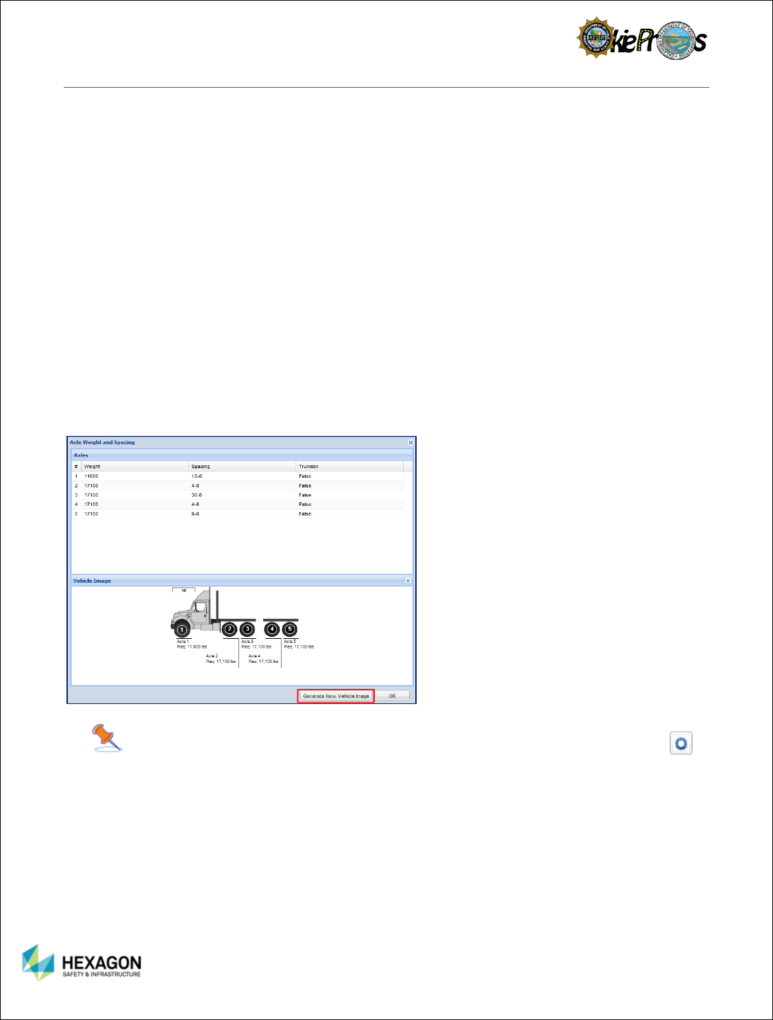
Number of Axles
Select the gear icon next to the Number of
Axles
The axle weights, spacing, and trunnion
check boxes display
Select Generate New Vehicle Image
Vehicle image will appear based upon the
vehicle dimensions.
19
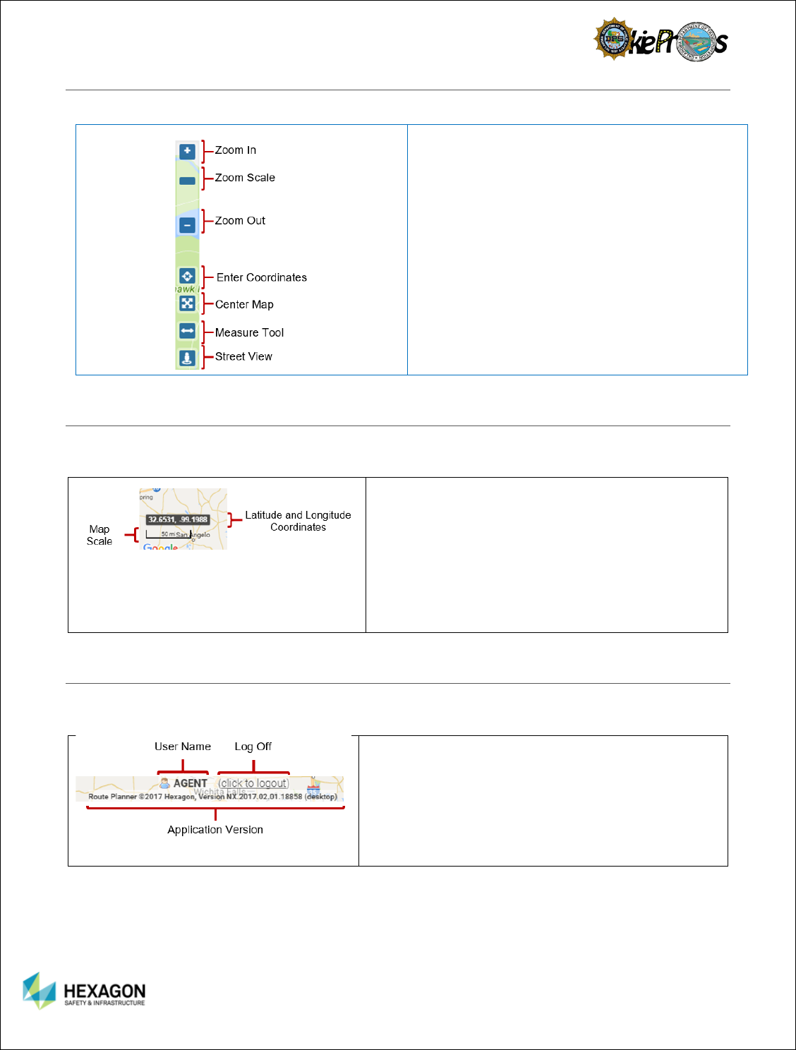
NAVIGATION TOOLBAR
In the table below, we will examine what each of the commands on the Ribbon Toolbar do.
Zoom In – Allows the user to view more details
on the Map
Zoom Scale – Allows the user to slide the zoom
from close to far.
Zoom Out – Allows the user to see less details
on the Map.
Enter Coordinates – Allows the user to directly
enter coordinates
Center Map – Allows the user resize the map
and center it.
Measure Tool – Allows the user to make
estimates about the mileage of a particular
road, roads, or area.
Street View – Allows the user to use Google’s
street view of the area selected.
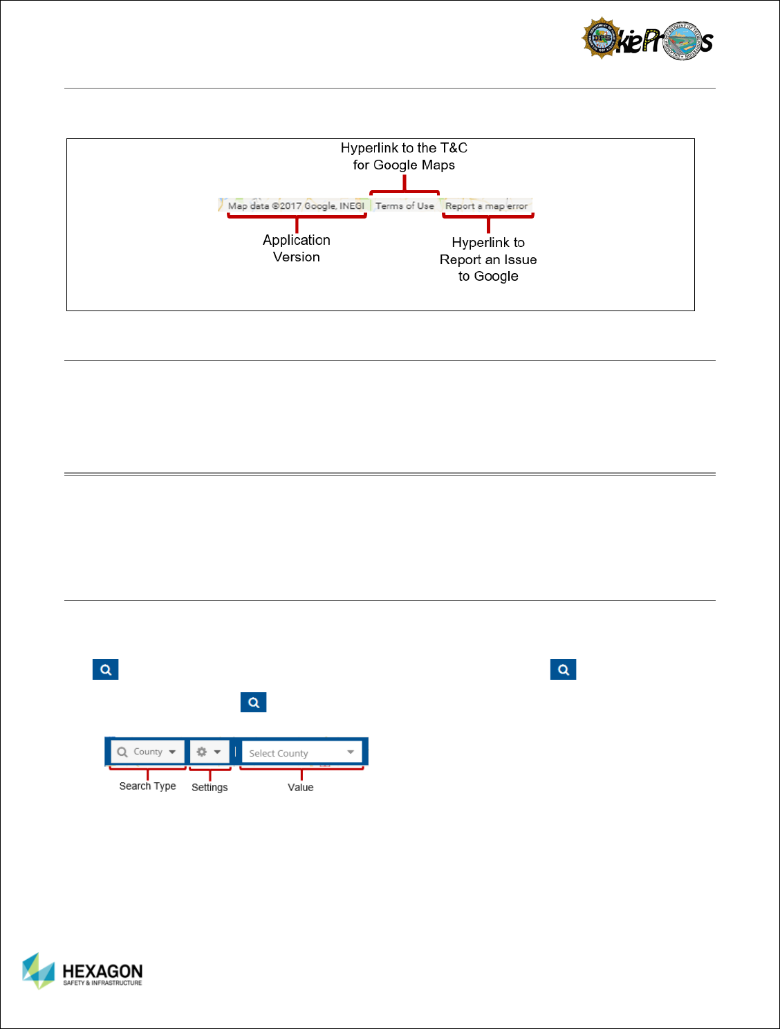
MAP SCALE AND MAP COORDINATES
The Map Scale and Map Coordinates are available to the user. They are found on the bottom left corner
of the screen.
Coordinates will display the respective longitude
and latitude values as the cursor moves around the
map.
Map Scale – Provides the user a frame of reference
for the distance relationship on the map. As the
user zooms in and out of the map, the units and
values will change accordingly from 50 feet to 1000
miles.
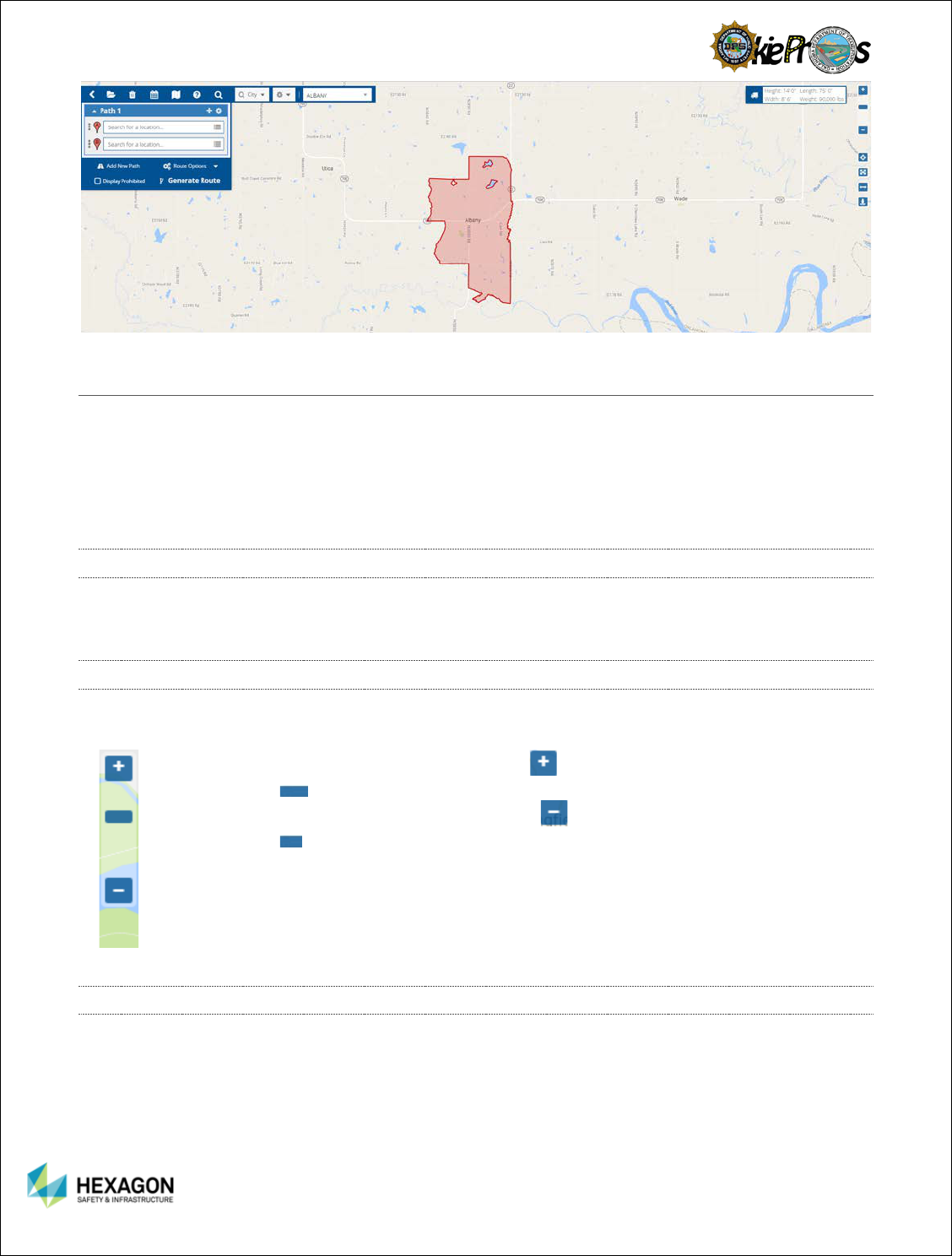
USER NAME | LOG OFF | ROUTE PLANNER VERSION
The Map Scale and Map Coordinates are available to the user. They are found on the bottom left corner
of the screen.
Username – Specifically important for internal users
to identify the username and appropriate role.
Functionalities may be slightly different for each
user’s role.
Log Off
Application Version – useful when logging JIRA
items to help HxGN identify the correct version of the
application.
20
GOOGLE INFORMATION | TERMS | REPORT A GOOGLE PROBLEM
The map used is based upon a Google Map which is layered with the Hexagon’s Routing data and
TomTom Data. Google information, Terms and Conditions, and Report a Map Error are available.
MAP
The Map panel graphically displays the route path and other geographic information to ensure the carrier
fully understands the route path. Standard map navigation functions include zoom in, zoom out, pan, and
zoom to area.
CHAPTER 4: MAP NAVIGATION OVERVIEW
When the user start Route Planner, the state of Oklahoma appears in the main map area. There are
several ways that the user can navigate the Route Planner map to get the view that the user need. The
user can use the mouse and several navigation tools to change the map viewing area as well as the
zoom level at which the map is displayed.
FIND TOOLBAR
The Find Toolbar allows the user to zoom to and/or highlight a City, County, Division, Troop, Turnpike,
Interstate, US Highway, State Highway, or Section Township Range. The Find Toolbar by default is not
expanded on the Upper Panel of the Cornerstone Panel. To expand the Find Toolbar, select the Search
Icon and conversely to collapse the Find Toolbar, reselect the Search Icon .
Select the Search Icon .
Verify Search Type, Settings, and Values display
Search Type includes: City, County, Division, Troop, Turnpike, Interstate, US Highway, State
Highway, or Section Township Range.
Settings includes: Zoom To, Show on Map, and Locatable
Value includes drop down lists for each specified Search Type such as pull down menus with county
names, city names, road names, etc.
21
ZOOMING IN AND OUT
There are a number of ways that the user can zoom in and out on the map:
1. Zoom in and out using the mouse
2. Zoom in and out using the navigation controls
3. Zoom by Rectangle
ZOOM IN AND OUT USING THE MOUSE
To use the mouse to zoom in, scroll the mouse wheel up (away from the user) a number of times. Alternatively,
to zoom out, scroll the mouse wheel down (toward the user) a number of times.
ZOOM IN AND OUT USING NAVIGATIONAL CONTROLS
The navigation control appears in the top left corner of the map. To use the navigation control, move the
cursor over the top of the navigation control.
1. Zoom in by clicking the zoom in button . The user can also use the zoom
scale to zoom in by selecting the scale and sliding the control upward.
2. Zoom out by clicking the zoom out button . The user can also use the zoom
scale to zoom out by pressing the left mouse button and sliding the control
downward.
ZOOM BY RECTANGLE
The Zoom by Rectangle feature allows the user to select a specific area of the map window. Users can
zoom in on a rectangular area by holding the Ctrl-key and dragging a box. The Zoom by Rectangle
feature is particularly useful to zoom into an area on the map quickly.
To Zoom by Rectangle, position the cursor in the approximate area the user wish to zoom in on, press
both the <Ctrl> key and the left mouse button at the same time and drag the mouse in the desired
direction. A rectangle with a blue edge will be displayed on the map.
22
PANNING THE MAP
Panning the map can be accomplished by clicking and holding the left mouse button down and drag the
map to pan in the direction of the user’s choice.
CENTERING THE MAP
Select the Center Map Icon in the Navigational Toolbar. The map will automatically resize and center.
DISPLAYING COORDINATES
As the user move the cursor across the map, the latitude and longitude coordinates change. Hover over
any area of the map to view the latitude and longitude. The coordinates are displayed in the lower right
corner of the map. Defining an origin or a destination can also be accomplished by entering in the
coordinates of a point.
Also if a user wants to go to specified coordinates such as their current location, the user can go to the
coordinates’ icon on the Navigation Toolbar, and select Use Current Location. The map will automatically
go to the location of the user. The Coordinates tool does not allow stop placement directly from the
function but it does give the user a reference point.
DISTANCE MAP SCALE LEVEL
The scale of the map aides the user in determining the zoom level of the map. The scale can range from
50 feet out to 5,000 miles. The change in scale is directly related to the zoom scale. The closer the zoom
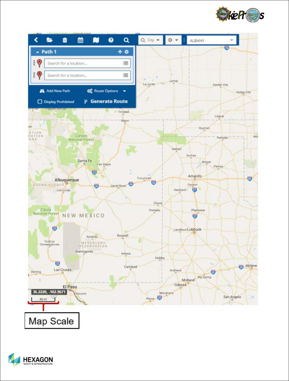
23
the less distance; and conversely, the more the zoom the further the distance.
24
MAP DISPLAYS
The Map Displays is located on the Cornerstone Panel, the user will find a way to change the way
the map’s appearance displays.
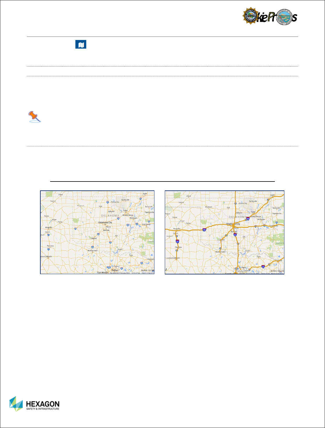
MAP LAYERS
Each map layer represents a particular theme or feature. The features have the ability to toggle on or off.
One layer could be made up of all the OSOW Roads, Designated Truck Routes, and Stops. The layers
can be layered on top of one another, creating a stack of information. Each layer can be turned off and on,
as if the user were peeling a layer off the stack or placing it back on.
Note: The stops will only display if stops are defined on the routing section.
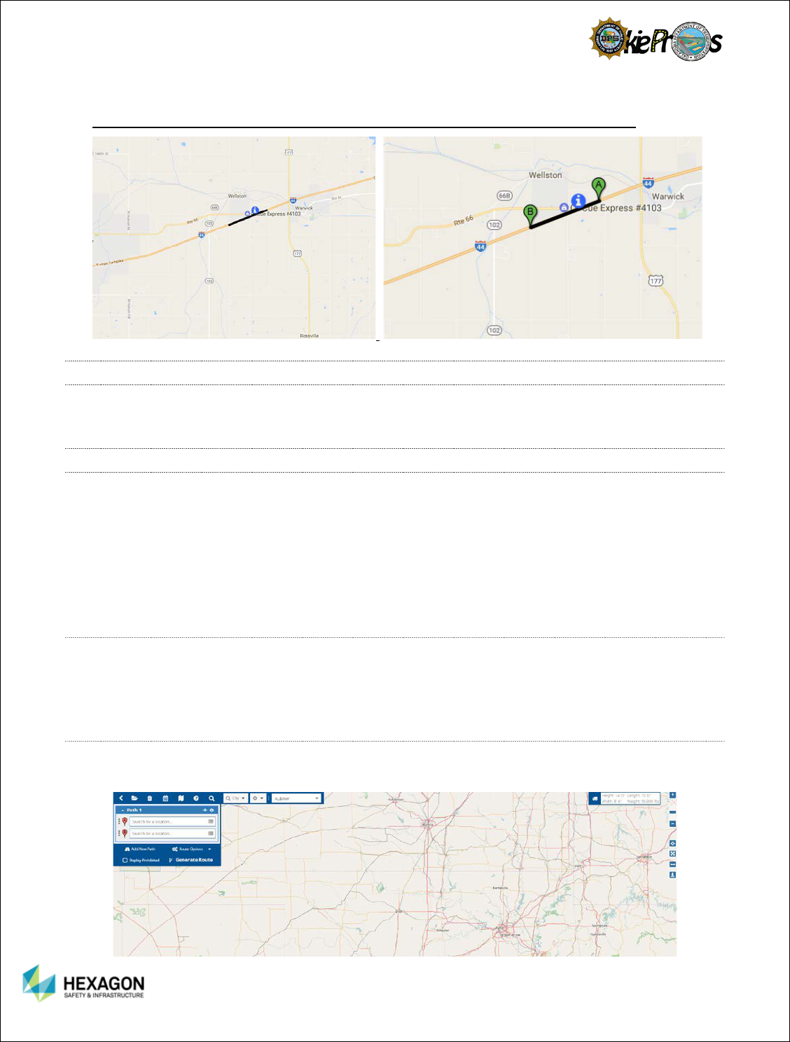
OSOW ROADS
See below for an example of the Google Streets base map without any overlay layers displayed and the
same map with the OSOW Roads layer displayed on top of the existing Google Streets base map.
Google Streets Base Map Google Street Base Map
(With no layers applied) (With the OSOW Roads layer applied)
25
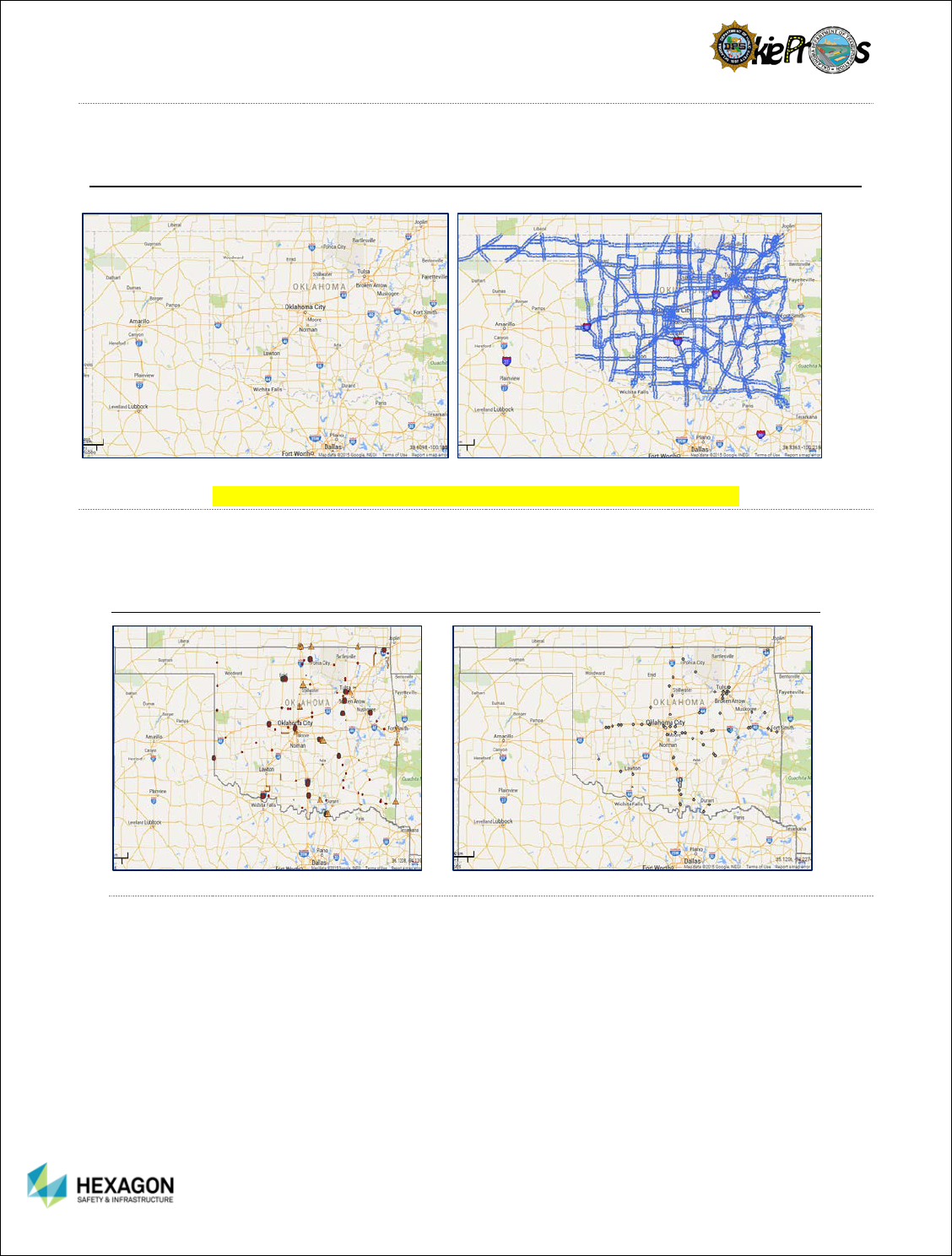
DESIGNATED TRUCK ROUTES
The Designated Truck Route layer shows interstates as well as State and U.S. Highways.
Google Streets Base Map Google Street Base Map
(With no layers applied) (With the Designated Truck Route layer applied)
PERMANENT RESTRICTIONS / TEMPORARY RESTRICTIONS
The Temporary Restrictions layer shows where there are temporary restrictions.
The Permanent Restrictions layer shows where there are permanent restrictions.
Google Streets Base Map Google Street Base Map
(With the Temporary Restriction layers applied) (With the Permanent Restriction layer applied)
STOPS
26
The Stops will display if a defined route is generated.
Google Streets Base Map Google Street Base Map
(With no layers applied) (With the Stops layer applied)
DISPLAY ORDER
Each of the Map Layers overlay on top of each other. To better define the map for the user’s best needs,
the display order may be rearranged.
BASE MAPS
The Restriction Manager can be used with one of several types of base maps:
Google Street
Open Street Map
Google Imagery
Google Physical
Google Hybrid
Google Satellite
OSOW Map
GOOGLE STREET
The Google Streets base map is the default map for the Route Planner. Most geographical features are
displayed such as roads; streets; hundred block numbers; expressways; state highways; US highways;
interstates; turnpikes; on and off ramps; state boundaries; bodies of water; rivers; town and city names;
major airports; railroad lines; major cemeteries; universities; hospitals; and national parks.
OPEN STREET MAP
The Open Street Map is a base map provided by the Open Street Map project. Cities and large towns
are labeled on the map, as are road names and points of interest when the user is zoomed in enough.
27
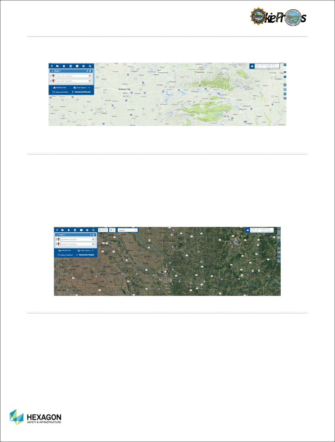
GOOGLE TERRAIN
The Google Terrain provides the user with a labeled road network with terrain attributes including rivers,
lakes, elevation, cities, and large towns.
GOOGLE HYBRID
The Google Hybrid base map is an alternate map that can be used for the Route Planner and is a
combination of a satellite view and Google Streets base map. The two highest zoom levels are not
available for the Google Hybrid base map. Most geographical features are displayed such as roads;
streets; hundred block numbers; expressways; state highways; US highways; interstates; turnpikes; on
and off ramps; state boundaries; bodies of water; rivers; town and city names; suburbs; major airports;
railroad lines; Air Force bases; major cemeteries; buildings; structures; universities and educational
facilities; hospitals; and national parks.
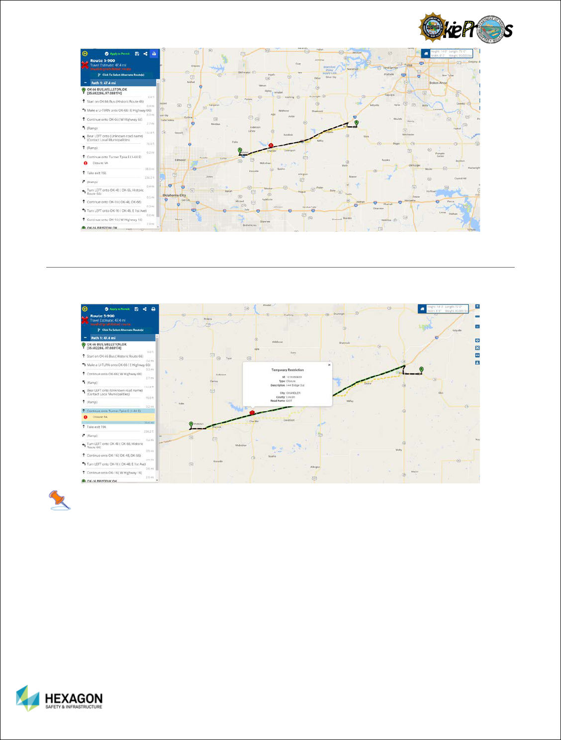
GOOGLE SATELLITE
The Google Satellite base map is an alternate map that can be used for the Route Planner and is a
satellite view without the Google Streets base map. The two highest zoom levels are not available for the
Google Hybrid base map. Most geographical features are displayed such as roads; streets; hundred
block numbers; expressways; state highways; US highways; interstates; turnpikes; on and off ramps;
state boundaries; bodies of water; rivers; town and city names; suburbs; major airports; railroad lines; Air
Force bases; major cemeteries; buildings; structures; universities and educational facilities; hospitals; and
national parks.

28
OSOW IMAGERY
The OSOW Imagery
OSOW MAP
The OSOW Map is an alternate state map that can be used and is supplied by the state. Most
geographical features are displayed such as roads; streets; expressways; state highways; US highways;
interstates; turnpikes; on and off ramps; county names and boundaries; county boundaries; state
boundaries; bodies of water; rivers; troop boundaries; and city names.

29
CHAPTER 5: ROUTING OVERVIEW
The routing engine uses the information the user provides to calculate a safe route. After the user define
the vehicle dimensions and build the route the user can view the detailed route map complete with driving
directions.
ROUTING OVERVIEW
The basic steps for building a route are:
1. Set the vehicle dimensions
2. Set the route start (Origin)
3. Set the route end (Destination)
4. Add Via Point(s) (optional)
5. Generate the route
6. Review the route details and driving directions
7. Save the route (optional)
ROUTE EVALUATION
The basic components required for automated restrictive routing include:
1. A highway network that accurately represents the on-routes for the State
2. A bridge network that accurately accounts for all the bridges within the State
Accurate bridge locations and properties are essential
The routing engine will analyze all bridges along the route for weight (if required) and size (horizontal and
vertical clearances). The routing engine will also check for any temporary restrictions along the route.
Temporary restrictions can consist of numerous conditions that may be encountered along a route. Some
examples are road closures due to construction, weather events, roadway width, length, or height
restrictions.
When calculating the route, the Routing Engine will offer the safest/shortest route for an OS/OW vehicle
that takes into account bridge height and clearances, load limits, one way road designations and
allowances, construction zones and weather events. An impedance model has been defined that
ensures the route returned is the least-costly path. By default, the route returned will favor major
highways in the order of Interstate, US highways, State routes, and local roads.
The routing engine will avoid bridges the vehicle is not permitted to travel on.
In order to perform a route analysis, a vehicle must be defined and a valid route must be defined. When
running in integrated mode, the vehicle is automatically known from the permit application. This leaves
only the route definition that is required.
PROHIBITED ROUTE
If a safe route for the vehicle is not possible, the system will prompt the user to generate and display the
Prohibited Route. A prohibited route is not considered safe and must be manually reviewed by an
appropriate agent or engineer before it can be approved and assigned to a permit.
If the user prefers, the user can select the Display Prohibited route option to view the hazards associated
with the route. This may help the user better understand why the user cannot get the route returned that
the user route prefered. An example of an invalid route is detailed below:
30
RESTRICTIONS
The user can view the restrictions reported along the route by selecting the Restrictions option in the View
region on the Ribbon Toolbar.
Tips:
1. If restrictions are reported along the route, the route will be identified as Invalid.
2. If no route could be generated, zoom into the route stops to verify that the stops are oriented to the
correct side of a divided highway.
3. If an invalid route is returned and there are no restrictions displayed along the route, report this to the
System Administrator.
4. When the user clicks on a restriction displayed in the Driving Directions panel, the restriction is
highlighted in green on the map and the restriction details are displayed in a call-out dialog that can be
closed by selecting the close option (x).
31
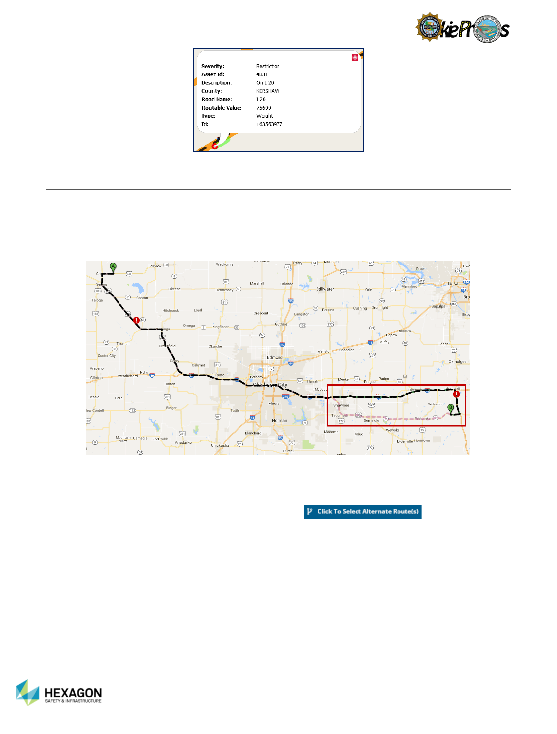
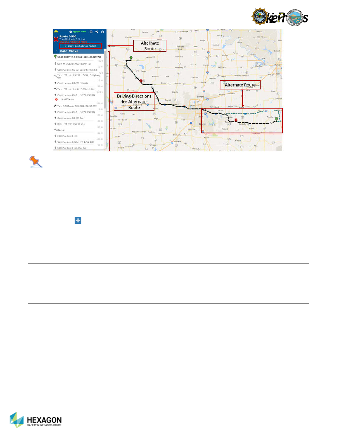
ALTERNATE ROUTES
Alternate Routes, is a privilege added by a System Administrator for different user groups, which allows
multiple routes to be defined based upon different impedance models: OSOW, OSOW Shortest, US
Highways, Interstates, State Highways, and Local Roads. The impedance models may be toggled on
and off to route the vehicle based upon one to six different options. When the route is generated the user
will see a message describing the different route number being generated.
If an alternate route generates, the route will appear as a dashed line and different colors depending upon
the number of routes returned. Note: Even if the user checks all six of the alternate routes, the alternate
routes may not all return with six different routes.
The user may select the Click to Select Alternate Route(s) so the driving
directions will represent the alternate route.
32
Note: Not all routes will display because the stops defined may only have a specified route where,
for example, local roads or state highways are not along the route.
The user can use the following actions to request a different route:
1. Use the Avoid Interstates option in the Ribbon Toolbar to request a route that keeps the vehicle off
the interstates.
2. Use Via Points to route through a particular place or along a particular or breadcrumb routes by
selecting the on the routing section in the Path area.
3. Use the Display Prohibited route option in the Route region on the Ribbon Toolbar to retrieve a
restricted route to see why the vehicle was not allowed to travel along a roadway.
IMPEDANCE MODELS
The Routing Service finds the best route by computing the quickest or shortest route on the network. The
alternate routes also work together with the impedance models.
DIRECTIONS PANEL
The Directions Panel displays the turn-by-turn directions and summary information about, the calculated
route, with average mileage. The user can show or hide the Directions Panel.
The Directions Panel provides specific directions for safely completing the route.
33
Tips:
1. The route traverses Stops (origin, optional via points, and destination) in the order the user defined.
2. When the user clicks on the route, the route will be highlighted with a label indicating the route type.
3. When the user clicks on a restriction in the Driving Directions panel, the restriction for the segment of
the route is highlighted in green on the map and the restriction details are displayed in a call-out dialog
that can be dismissed.
4. If the user hovers the mouse over a driving direction the roadway and total mileage will be displayed
as a tooltip style message.
5. If the route returned contains one or more restrictions the route will be classified as Invalid.
6. A trip cannot begin and end in the same location.
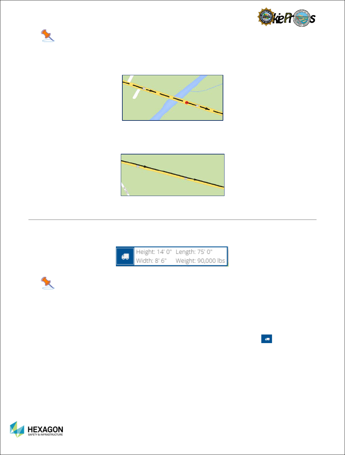
MAPPED ROUTE
The Route Planner uses different line symbology to distinguish between a Safe Route and an Invalid
Route. An Invalid Route will always be displayed using dashed lines, whereas a Safe Route will always
be displayed using a solid line.
34
Tips:
1. The user may have to zoom in closer, to see that a broken line is being used to display the INVALID
Route. (Especially, if the route crosses the entire state.)
2. If the user zoom in closer, the line symbology used to display the route will include a directional arrow
that indicates the direction the vehicle is traveling.
VEHICLE INFORMATION
The user can view/set the vehicle dimensions by selecting the Vehicle option in the View region on the
Ribbon Toolbar.
Tips:
1. When running in integrated mode the vehicle dimensions that were entered on the permit will be
displayed as read-only. The Routing engine will use this vehicle data to calculate a safe route.
2. When running in standalone mode, the user can configure the vehicle dimensions in the Route Planner
application. The Routing engine will use this vehicle data to calculate a safe route.
3. To view the vehicle’s axle configuration used for bridge analysis, select the Truck icon. A vehicle
will be classified as valid or invalid depending on the axle weight and spacing configuration. If the
vehicle is classified as Invalid, the routing engine will calculate a route that avoids Bridge Formula
restrictions.
4. Changes made in the Vehicle Information dialog take effect immediately. The Routing engine will
always consider the active vehicle settings.
5. The Load, Save Manage, and Share commands located in the Cornerstone Panel and Driving
Directions apply specifically to the route, not the vehicle.
35
BRIDGING
The OKDOT Bridge Enginnering group has assigned a vehicle classification to each bridge that reside on
the Oklahoma state roadway network. The vehicle classification is used to regulate the vehicle that can
be put on an individual bridge. The vehicle classification is necessary to prevent heavy vehicles from
damaging roads and bridges.
A Divisible Load is a load that can reasonably be dismantled or disassembled and does not meet the
definition of non-divisible.
A Non-Divisible Load is any load or vehicle exceeding applicable length, width, height, or weight limits
which cannot be separated into smaller loads or vehicles without compromising the intent of the load or
vehicle.
All legal loads will consider the bridge posted weight limits to ensure that appropriate routes are used.
The legal load will not be routed over a load restricted bridge when exceeding the posted capacity of the
bridge, unless a special exception is granted by OKDOT.
All Non-OL1 vehicles will consider the OL1 bridge restrictions to ensure that appropriate routes are used.
Non-OL1 loads will not be routed over a restricted bridge, unless a special exception is granted by
OKDOT.
To generate a new vehicle image, select Generate New Vehicle Image. When selected, the new vehicle
image will be displayed.
Tips: The Axle Weight and Spacing dialog is displayed when the user select the gear
icon located on the Vehicle Information dialog.
36
CLEAR ROUTE
To clear the route and start / end location markers, click Reset All located in the View region on the
Ribbon Toolbar. When selected, the Routing panel and the map will be returned to the default settings.
The route will be cleared from the map and the routing panel. The map will be returned to the state view.
The vehicle dimensions will not reset when the user select Reset All.
To clear one stop select the hamburger or context menu beside the stop the user wants to clear.
Select Clear in the drop-down menu.
PRINT ROUTE
To print the route map and directions, click Print located in the Driving Directions once the route is
generated from the Cornerstone Panel. If the user want to include the map in the printout check the
Show Map option.
37
CHAPTER 6: BUILDING A ROUTE
Before the user can generate a route, the user must build the route. Building a route consists of defining
the route stops. A minimum of two stops (Origin/Destination) is necessary to create a route. Optionally,
the user can define the route to include Via Points. Via Points allow the user to lay a virtual ‘breadcrumb
trail’ to define the roadways that the user would like the vehicle to travel along.
BUILD THE ROUTE
The first step in building a route is to establish precisely where the route will begin and where the route
will end.
Define the Route Origin
To define the Origin, click on the <Enter Origin>
prompt in the Routing panel. Select the desired
locate option from the drop down menu.
To define the Origin, click on the <Enter Origin>
prompt in the Routing panel. Select the desired
locate option from the drop down menu or directly
enter the address | coordinates | or point of
interest.
Define the Route Destination
To define the Destination, click on the <Enter
Destination> prompt in the Routing panel. Select
the desired locate option from the drop-down
menu or directly enter the address | coordinates |
or point of interest.
Optionally, Define a Via Point
To add a Via Point, select the + Icon and Select
Add Via Point. The Routing panel will be updated
to display the newly added via point. More than
one Via Point may be added to make a virtual
breadcrumb route.
GENERATE THE ROUTE
As soon as the user has defined at least two stops, the user can select Generate Route to calculate an
accurate and safe travel route. The routing service is designed to automatically route the vehicle around
active roadway restrictions ranging from construction projects, bridge weight restrictions, bridge
width/height restrictions, weather events, and more.

38
LOCATE OPTIONS AVAILABLE IN THE ROUTING PANEL
When building a route, the following locate options are available in the routing panel to define the route
stops: Map Click, Street Address, Intersects With, Coordinates, and Point of Interest (Free Form Entry).
MAP CLICK
When the user does not have an address, street intersection, point of interest, or coordinates, the map
click option is a nice feature that allows the user to easily define the stop by clicking on the map.
1. When placing a stop on a divided highway, zoom in close so that the user can clearly see the divided
highway displayed on the map.
2. Sometimes the map click option is unable to locate a stop. When this happens, zoom in closer and try
again.
3. Be sure to place the mouse pointer on roadway that the user is interested in.
4. Be sure to place the mouse pointer on a roadway that resides within the state of Oklahoma.
5. The map click may return several address options. The addresses will be denoted with either a
Hexagon Logo or a Google Logo to let the user know what database the address came from. If
the user finds that none of these addresses are correct, they may cancel this search. Try again by
zooming in closer to the map to narrow the address choices.
STREET ADDRESS
The user can enter a street address or a common place by using the Locate by Street Address option.
1. If the street address cannot be found in Google maps, then odds are it will not be found in the Route
Planner application. (Behind the scenes, the Route Planner application is using the Google Places
service to locate an address.)
2. When entering a street address, the user has the option of entering the street number in the Number
field and the street name in the Street Name field or entering both the street number and the street
name in the Street Name field.
3. If the user discover that the street address cannot be found when the user enter both the street number
and the street name in the Street Name field try breaking the information up by entering the street
number in the Number field and the street name in the Street Name field to see if the street address
can be found.
4. When entering a street address, the user does not have to include a city name. The city name is useful
to filter the list of results that are returned.
5. When entering a common place, the user has the option of entering the common place in the Street
Name field or the City Field.
6. When entering a street address, the user can simply enter the city name. The locate service will return
the street address of the city center.
7. All addresses entered must be related to the state of Oklahoma.

39
INTERSECTS WITH (STREET INTERSECTION)
1. When defining a street intersection, the user has the option of selecting a roadway that crosses a
state border, county border, or city border. Additionally, the user has the option of selecting the
intersection of two crossing roads.
2. The locate service will convert the street intersection to a valid street address.
3. The locate service will not be able to locate the street intersection, if an invalid intersection was entered.
COORDINATES
1. Latitude/Longitude
If the user knows the latitude and longitude coordinates of a location, select the
Latitude/Longitude option on the Locate by Coordinates dialog and enter the values.
The Lat/Long values are entered in decimal format. In general, the format of the Lat/Long is
a decimal number with 5 decimal places. No leading zeros are required. Example:
34.076123, -81.183196
When entering the Lat/Long coordinates, the user must enter both values.
2. X/Y
If the user knows the X and Y coordinates of a location, select the X/Y option on the Locate
by Coordinates dialog and enter the values.
The X/Y values are also entered in decimal format. In general, the format of the X/Y is a
decimal number with 5 decimal places. No leading zeros are required. Example:
613707.924082429, 248718.109847927
When entering the X/Y coordinates, the user must enter a value for both X and Y.
3. The locate service will not be able to locate the stop, if a roadway does not exist at the location entered.
4. The locate service will not be able to locate the stop, if invalid coordinate values are entered.
5. The system will automatically calculate the X/Y coordinates for all stops that are located.
LOCATE OPTIONS AVAILABLE IN THE MAP
The user can right-click on the map to get a pop-up menu of locate options including: Set Origin, Add Via
Point, Set Destination and View Restrictions. These options can be used to build the route.

40
SET ORIGIN
1. If the user wants to find a stop for a location on the map, use the Set Origin function.
2. The function for Set Origin works identically to the map click option.
ADD VIA POINT
1. If the user wants to find a Via Point to make a virtual “breadcrumb” route that will likely differ from the
routes returned by the application. However, the Via Points may use the route returned as a
reference or as a way to avoid the restrictions from a prohibited route.
2. The function for Add Via Point works identically to the map click option.
SET DESTINATION
3. If the user wants to find a stop for a location on the map, use the Set Destination function.
4. The function for Set Destination works identically to the map click option.
RESTRICTION WITHIN RADIUS
1. If the user wants to find the restrictions near a location on the map, use the Restriction by radius
option.
2. Sometimes the Map Click option is unable to locate a restriction for the selected radius. When this
happens, select a higher radius.
3. The restriction address will be placed in the order added to the route. The first two stops added are
treated as the route origin and destination. Additional stops are treated as Via Points and placed in the
order the user add them to the route.
4. The application will only return restrictions that apply to the current vehicle dimensions. If the vehicle
would legally clear a restriction found within the radius, it will not be shown to the user.
STREET VIEW
Street View Tips:
This enables the user to visually tour the area using the Google Street View anywhere along the
route or a specified area.
To view street-level imagery for a specific location, zoom into the area of interest. Click on the
Street View Icon located in the navigational tools to the right of the screen, then click on the
specified point to view the street view.
The user may rotate the view, advance the view, or retreat the view to gain the visual information
needed.
SAVED ROUTES OVERVIEW
Saved Routes can come in very handy. A good rule of thumb is to save the route if the user finds that
they are getting numerous route requests that are routinely traveling between the same origin and
destination.
41
SAVED ROUTES
Saved Route tips:
1. Give it a name that is easy for the user (and the colleagues) to find.
2. The route name cannot be longer than 40 characters long.
3. Manage the list of saved routes. As time goes by, the user may discover that the routes fall into the
category of Here Today, Gone Tomorrow. Periodically, take time to delete the saved routes that the
user is no longer using.
4. Route related commands are located in the Driving Directions Panel. The save route function may be
accessed after a route has been generated by selecting the Save Icon .
LOCATE A STOP – RECENT | FAVORITE | BOUNDARY | ZOOM TO
The user may notice that when the user uses any one of the Map Click options to locate a stop, the stop
is automatically marked on the map with a green balloon but, when the user use the non-Map Click
options (Street Address, Intersects with, or Coordinates) the stop is not being displayed on the map.
At any point when the user is building the route, if the user want to find out where a stop is located on the
map, or if a user wants to use a recent stop, a favorite stop or a boundary stop, the options are available
for each stop including via points.
Tip: If a user is a first time or not a very active user, there may be no data in the Recent and
Favorites until the user begins defining routes. The Recent Stop will start displaying once the routes are
generated. However, Favorite Stops will need to be defined from the Recent listings. Favorite Stops will
be discussed in more detail in this section. Default Boundaries are listed and the user may add more
depending upon their needs.
42
Before Beginning
Click on the Stop’s Hamburger or Context Menu.
The user will find multiple ways to find stops.
RECENT
The user may select recent to view recently used stops to choose.
When the user selects Recent, a table will populate with up to a couple of dozen entries to choose.
FAVORITES
Select the stop either origin, destination, or via point
When the user selects Favorites, a table will populate with the list of the user’s favorite stops.
To make a stop a Favorite, review the Recent List, highlight the record, then select the Fav Icon.
A message box will prompt the user to add the stop and the user may also rename the Stop.
The Fav Pin will change colors in the Recent Stops from gray to blue, indicating a favorite stop.
Boundary
Works similarly to the Favorites stops. Select any stop and it is recommended that the stop be a
city, county, state, district, et al stop.
When the user selects Boundary, a table will populate with the list of the system’s Boundary stops.
To make a stop a Boundary, review the Recent List, highlight the record, then select the Bnd. Icon.
A message box will prompt the user to add the stop and the user may also rename the Stop.

43
The Bnd Icon will change colors in the Recent Stops from gray to blue, indicating a Boundary stop.
ZOOM TO
Select the Zoom To
The user will be relocated to the respective stop.

44
APPENDIX A: TERMINOLOGY
Bridging – In integrated mode, the vehicle information entered in the Permit System will be passed to the
Route Planner application. The routing service always considers the vehicle dimensions when generating
a safe route. If a vehicle fails validation, the routing service will route the vehicle so that it avoids the
Bridge Formula restrictions.
Notification – Notifications are informational in nature. They are used to inform the driver of issues that
may impede travel, but not necessarily prevent travel.
Permanent Restriction - Permanent restrictions are typically created from a known enterprise data
source and are used to set minimums or maximums on the roadway network for aspects such as width,
height, and weight.
Prohibited Route / Invalid Route – A prohibited route/Invalid route is a route generated by the system
that is NOT considered safe and must be manually reviewed by an appropriate agent or engineer before
it is approved and assigned to the permit.
Restriction – Routing restrictions are limitations such as weight, height, width that are used to ‘restrict’
travel.
Safe Route – A safe route is a route generated by the system that is considered safe.
Temporary Restriction - Temporary Restrictions typically occur in real time and affect travel in the
network, but do not exist in an enterprise data source. The restriction varies from construction zones,
roadway alerts or weather events.
Warning – Warnings are advisory in nature. They are used to alert the driver of travel advisories such as
when an escort is required.
APPENDIX B: REPORT PROBLEMS
1. To contact the Oklahoma Department of Public Safety with questions or comments, use the HELP
LINE – 405-522-9060.
2. When reporting a problem be sure to include:
3. Date and time of the error.
4. Application version number.
5. A one-sentence description of the problem in the subject line.
6. The page where the user is encountering the problem.
7. A step-by-step description of the actions the user performed that led to the problem.
Include data the user was entering.
8. Error message(s) that appeared. (Screenshots are encouraged!)
